Category Archive: Uncategorized

Dear customers, vendors, and partners,
Thank you for allowing us to do what we do. As we enter the Thanksgiving week, we are reminded again that we would not be in the amazing position that we are today without the trust, support, and commitment that we receive from you every day. Whether you are customer number one, a supplier that we only buy from sporadically, or somewhere in the middle, please know that we are thankful for all that you do in allowing us to succeed. We truly could not do it without you.
From our team to yours, have a Happy Thanksgiving!
-WS Hampshire
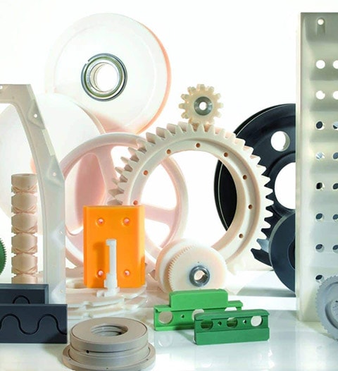
Although the chemical-mechanical properties of plastic are largely determined by their chemical composition, their properties can be modified via heat treatment. One of the most commonly used heat treatment methods to alter the mechanical properties of plastic is annealing. (more…)
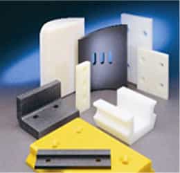
Nylon – chemically polyamide (PA, not to be confused with polyimide, PI) was invented in 1935 by DuPont’s Wallace Carothers (PA 6/6). Nylon 6 (PA 6, extruded), or polycaprolactam, was developed by Paul Schlack at IG Farben to reproduce the properties of nylon 6/6 without violating DuPont’s patent. Initially used in fibers to replace silk in parachutes, stockings etc, these resins established the basic principles of polymer chemistry that have made plastics such a ubiquitous part of our lives today. Nylon was also injection molded into components for the automotive market with varying degrees of success…people back then disliked nylon timing chain sprockets as they constantly stripped out!
(FUN FACT – “NYLON” was originally DuPont’s tradename, but DuPont didn’t protect it and it became so commonly used that they lost the right to it – today it is “ZYTEL®”)
Generally, nylon machined parts have a robust combination of properties, including high strength-to-weight ratio, toughness and inherent wear resistance. Stock shapes in 6/6 nylon are all extruded; in type 6, it can be either extruded (Europe) or cast (worldwide). While there are slight property differences, usually the decision between PA 6/6 and 6 involves either size and/or specifically modified version availabilities.
PA 6/6, sometimes referred to as Nylon 101 (old DuPont callout), is available in natural (off white), black, glass filled and specialty grades (low smoke, flame retardant, heat stabilized, impact modified). There are no enhanced wear resistant versions currently available.
NOTE: The crossover point [cost versus size] between unfilled extruded PA 6/6 and cast PA 6 is about 2.5” diameter rod, and .500” plate, over which cast PA 6 costs less to make.
PA 6 – in North America, 99+% of PA6 is cast, so we’ll stick to that technology. Cast nylon was first invented in Europe in the 1950’s and introduced in the US in the early 1960’s. Since it is made by combining two liquid feedstreams into a tool which react to become PA 6, additives are much easier to incorporate, and a wide range of sizes and shapes are readily available (from thin plate to custom castings weighing hundreds of pounds).
Here are the most popular grades of cast PA 6 currently available:
MODIFIER | COLOR | BENEFIT |
| Unfilled | Natural, black | General purpose |
| MoS2 filled | Grey, black | Higher crystallinity |
| Heat stabilized | Blue, black | Higher cont. Temp. Use |
| Oil-filled | Natural, green, others | High load / low speed |
| Oil & MoS2 filled | Dark blue, black | Crystallinity + lubricant |
| Solid lubricant filled | Red, grey, black | Highest PV rating |
| Solid lubricant filled | Purple | Lowest “stick-slip” |
| Impact modified | Blue, yellow | High impact resistance |
There are also alloys of PA 6, such as PA 6/12, which can offer lower moisture absorption and higher impact resistance.
Again, it is nylon’s combination of properties that make it so widely used. There are many applications that have 4 or 5 key property requirements, where nylon isn’t #1 on any of them but #2 on all of them!
Too many choices? No worries – the nylon experts at WS HAMPSHIRE can guide you through the selection process. You’re in the right place!
Tom Connelly is a self proclaimed “Street Engineer” with over 40 years in the plastics industry.
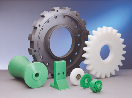
Ultra High Molecular Weight Polyethylene (UHMW) is one the most widely used thermoplastic materials today. It is defined as having a minimum molecular mass (molecule length) of 3.2 million; some resins go as high as 7.5 million (for reference, HDPE = ~1MM, LDPE = ~500,000)
UHMWPE advantages in its virgin form:
- odorless, tasteless, and nontoxic
- highly resistant to corrosive chemicals except oxidizing acids
- almost no moisture absorption
- extremely low coefficient of friction (comparable to PTFE (“Teflon®”))
- self-lubricating
- excellent abrasion resistance, especially wet (~15X better than carbon steel)
- highest impact resistance of any thermoplastic (IZOD = no break)
Easily modified, this base material is used in applications as diverse as cargo dock impact bumpers to dump truck liners to food equipment to orthopedic joint replacements. Essentially a “poor man’s Teflon®”, it shares similar properties, with some significant limitations.
Like PTFE, UHMW cannot be melt processed, as this breaks down the molecular chain. It is made using compression and heat to “fuse” the material below its melting point. It is available in compression molded sheets up to 8’ x 20’, and ram-extruded rod, tubes & profile shapes.
The largest industrial markets for UHMW are food processing and heavy equipment, both primarily for bearing & wear components. For such applications, the limitations versus nylon or acetal are:
- Heat Resistance – the heat deflection temperature is 116⁰F, compared to ~200⁰F
- Thermal Expansion – UHMW changes at 2X the rate of nylon with temperature changes
- Compressive Strength – its compressive strength = 3000 psi, versus 15,000 psi for nylon – UHMW’s safe working load is 1000 psi maximum
- Inserts – since the material is only 25%as strong as nylon, larger / specialty inserts with a foot extension on the bottom (prevents pull-through), and limited torqueing is needed
Where food contact is not an issue, reprocessed UHMW is a cost effective alternative. Using clean regrind mixed with virgin black resin yields a material with the same low friction, low moisture absorption and impact resistance of virgin at lower material cost. Due to the inclusion of the larger regrind particles, it is actually slightly harder and some OEMs prefer it over virgin.
There many modifications of UHMW available, including colors; UV stabilized; lubricant filled (solid, oil or MoS2), ceramic filled; anti-static/conductive; metal/X-ray detectable; high temperature.
This last version needs come clarification. Some mills offer an anti-oxidant filled UHMW touted to withstand 275⁰F – HOWEVER -THE HEAT DEFLECTION TEMPERATURE IS THE SAME AS VIRGIN, 116⁰F! What the 275F means is that, where pure virgin UHMW starts to oxidize (turn brown) over time @ ~175⁰F, this version adds ~100⁰F heat resistance before oxidation.
Too much information? Give us a call, the experts at WS HAMPSHIRE can walk you through all the data to find the right material for your needs – you’re in the right place!
Tom Connelly is a self proclaimed “street engineer” with over 40 years in the plastics industry.
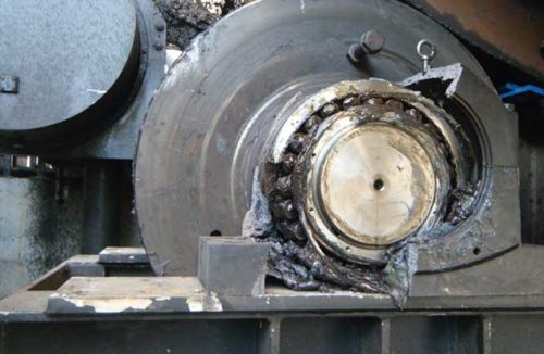
SELF LUBRICATING MATERIALS CAN HELP!
Either as an OEM making equipment, or as an end user, lubrication of moving parts is a major consideration – and ongoing cost – in the life of the equipment. Do you find yourself buying more lubricants than you should, or replacing “friction and wear” parts too frequently?
Grease is so ubiquitous that most people don’t even know the definition or composition. The ASTM definition of lubricating grease is: “A solid or semi-solid lubricant consisting of a thickener agent in a liquid lubricant. Other ingredients imparting special properties may be included”. Commercial grease usually consists of a thickener ( 5 to 35 wt %), base oil ( 65 to 95 wt %) and various additives (0 to 10 wt %).
Lubricants can be “natural” (petroleum-based) or “synthetic” (silicone, etc). There are four basic types: liquid (oil), semi-solid (grease), solid (Teflon® tape) or powdered (graphite or molybdenum disulfide powders). Once you start adding generic specialization, then each supplier’s “whiffle-dust” and a marketing plan, and you have literally thousands of options!
Yet with all this availability, over 50% of bearing failures are directly attributable to lubricant failure or contamination, as documented by Ernest Rabinowicz, an MIT professor for 43 years, widely known for his work in tribology, (study of friction and wear) and author of THE authoritative book “Friction and Wear of Materials”.
Professor Rabinowicz also documented that, on average, ~6% of the US GDP is spent on repairing damage from mechanical wear. In 2019, GDP was $21.5 trillion; 6% = ~$1.3 trillion!
Another consideration is the cost of delivering the lubricant to the wear surfaces –studies show that, on average, the application costs are 5X the cost of the lubricant itself – so, if the lubricant costs $2, the total cost to apply it is $10 – and that doesn’t include the costs in spills/clean-up, OSHA/EPA reporting, and other hidden costs that are usually buried in the maintenance budget.
Traditional metallic wear parts usually need frequent lubrication – what if you could reduce or even eliminate it?
How can you find a source that might help? You just did!
WS HAMPSHIRE provides industrial parts from many composite materials, both thermoplastic and thermoset, that have specially designed internal lubrication packages to address this problem. Some customers have been able to eliminate external lubrication entirely; many more have reduced the frequency and amount of lubricant, with our self-lubricating materials acting as a “safety factor” in case a lube system failure.
One example: an OEM of 125 ton mining trucks had a severe lubrication issue on the rear dump pivot bushings. Sealed roller bearings weren’t “sealed enough”, and grit got in and wore the rollers. Bronze would work, but required force-greasing 2X per day to flush out the grit (especially coal dust), that wore on the steel pin more than the bronze. They then extensively tested a solid lubricant filled cast nylon, which required no grease, and any grit that entered was simply buried in the nylon below the wear surface – problem solved and the thermoplastic solution cost less than the bearings or the bronze!
Give the pros at WS HAMPSHIRE a call – you’re in the right place!
Tom Connelly is a self-proclaimed ‘street engineer’ with over 40 years in the plastics industry.
Most materials will expand when heated and shrink when cooled. Consider expansion joints on bridges – even concrete with rebar will move with temperature changes. The coefficient of lineal thermal expansion is used to calculate how much expansion or contraction will occur when a plastic part is heated or cooled. The lower the figure, the more dimensionally stable that material will be.
Generally, even the most stable composites move about a degree of magnitude more than most metals with heat, and composites are heat insulators!
The most common method to generate coefficient of linear thermal expansion data is ASTM E-831, Thermal Mechanical Analysis. Simply, a small sample is placed in a chamber where the material is cooled to typically -40F. A sensor rod touches the material and measures the growth as temperature increases to ~300F.
The data is actually generated as a curve (see below), but from that is reported a single, averaged value (see chart). Domestically, this value is reported as 10-5 inch/inch/⁰F. For most applications, this information is sufficient for designing proper fit for parts that will see temperature swings.
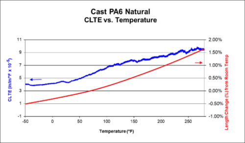
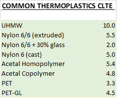
Note the effect of fiber reinforcement on stability (raises it as it does with other properties).
So, what does all that mean to the designer?
You can use these values to calculate growth. Say you have a 4” long wear pad made from cast nylon, and the part has been stored @ 73F but will see 125F in service. You take the coefficient of linear thermal expansion of .0005” x the 52F increase – the part will grow .0025” @ 125F. The same part in UHMW would grow .0052”.
Fit – you must therefore allow for growth in whatever structure the part functions – if it’s a bushing pressed into a housing, growth will be all on the ID and extra clearance must be added; on very long parts, the length will grow noticeably.
Attachment – it is best practice in wear pads to allow for growth by designing slightly oversize holes; with materials like UHMW, slots may be needed (like vinyl siding has), or the part may buckle. With thermoplastic bushings, allow for “close in” as frictional heat is experience.
Technical Note
Thermoplastics are isotropic – they grow equally in all axes. However, phenolics (while generally more stable) are anisotropic – they grow slightly differently in length (X axis) and width (Y axis), so orientation of the raw material is critical in determining growth of a finished part.
Confusing? Don’t worry, the team at WS HAMPSHIRE can help you! You’re in the right place!

“The part failed!” All plastic parts suppliers have received this frantic call and while you want an explanation and immediate solution, it’s critical to find out exactly what went wrong before beginning to determine how to address the problem.
First, it’s important to know that most failures are due to a series of events. The part may have broken, but what happened before it failed? For example: a crane operator disconnecting the “boom safety slip”, causing severe side loading on the outside sheave rim. The sheave fails, but the disconnection actually caused the failure.
SOME TYPICAL FAILURE MODES:
Click to Expand

Heat – The #1 enemy of thermoplastic wear parts and must be properly managed. An immediate signal is when excessive heat the material brown. This is often caused by excessive speed and/or pressure.
Pressure –Pressure alone can cause initial failure which is often seen as distortion at the “over-pressure” point. Remember that plastics are subject to creep over time, especially with relatively low increases in temperature –the safe design criteria for a material is 25% of its ultimate compressive strength
- Additionally, look for misalignment that results in localized pressure
Shock or Impact – This typically results in a “glass fracture” of the material, especially with more crystalline materials such as extruded moly filled nylon or PET based materials
Chemical Attack – Some materials are susceptible to steam, solvents, oils or acids – if so, the surface exposed usually has a distinct appearance
UV Exposure – Some materials become brittle, especially in very thin cross sections. This is usually first seen as surface discoloration.
- NOTE – “black” doesn’t automatically mean UV stabile unless it’s specified as a UV grade
CONTRIBUTING CAUSES
Inadequate Design
- Taking a “robust” design and scale it back to achieve cost or part uniformity goals, reducing safety factor
- Not taking into consideration the abnormal conditions that a component may face. A common example being heavy equipment which can be in service in Northern Alaska or in Arizona.
- not allowing for growth due to heat, moisture, etc
- inappropriate attachment method
Misapplication – A part may work in one application but may not be right for another and lead to failure. For example, nylon sheaves that work for a pipe lifting winch installed where steel sheaves should be used on a top-head rotary mechanism with high fleet angles and severe loads.
“Less Than Optimal” Material Choice – The concept of “should good enough” leaves no margin for error. Think of this one- substituting oil filled nylon for solid lubricant filled nylon– both “lubricated”, but the limiting PV (pressure x velocity) drops from~15,000 to ~6,000.
Mating Surface Issues – Qualifying parts against a given surface then using another in the real world can have consequences. An OEM once got a deal on steel which matched the necessary physical requirements but had so much scale that it severely abraded the nylon wear pads almost immediately.
Raw Material Issues –On rare occasions a mill can ship material that doesn’t meet normal standards. It’s usually caught in fabrication, but not always. Again, with proper safety factors this should not result in catastrophic part failure
Need help with a plastic part issue? Call the pros at WS HAMPSHIRE, we know what to ask to address the issue! You’re in the right place!
Tom Connelly is a self proclaimed “Street Engineer” with over 40 years in the plastics industry.
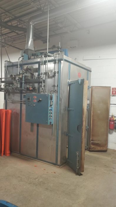
ANNEALING OF THERMOPLASTICS – WHAT IS IT, WHY DO IT?
Click to Expand
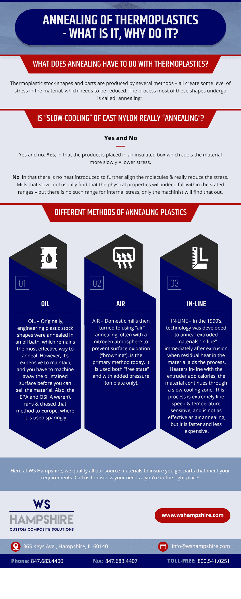
Thermoplastic stock shapes and parts are produced by several methods – all create some level of stress in the material, which needs to be reduced for several reasons. The process most of these shapes undergo is called “annealing”.
The process is straightforward but isn’t “easy”. You heat the material to a temperature below its glass transition point, hold it there for time that is dependent on the material and thickness, then cool it. Both the heating and cooling must be done slowly, or the material will be thermally shocked which can cause, instability (rather than stability).
In plastics, extruded and injection molded shapes have the highest process-induced internal stress and require extensive annealing. Before cast nylon was available in FDA natural, companies would use extruded 101 (6/6) nylon rod up to 6” in diameter, and it wasn’t unusual even for thoroughly annealed 6” rod to explode every so often when contacted by a tool.
Compression molding is usually used to produce materials that cannot be melted – most often PTFE (“Teflon®”) based material, and UHMW-PE. These materials are “fused” under pressure and heat, similar to powder metallurgy. Despite this lower stress process, thick sections still require some extra attention to relieve stress.
Other materials are cast – several nylons, urethanes are examples. You pour the different base materials, and they react to become that material in the mold. With nylon, again, heavier sections require special handling. And, with cast nylon, secondary annealing also bakes off the residual unreacted monomer, which attracts excess moisture, and makes the nylon ma harder.
Occasionally, when machining parts that have unique designs – deep pockets, large cross-section differences – it’s appropriate to “rough” machine the part, reanneal it, then finish machine to print.
Is “slow-cooling” of cast nylon really “annealing”? – yes and no. Yes, in that the product is placed in an insulated box which cools the material more slowly = lower stress. No, in that there is no heat introduced to further align the molecules & really reduce the stress. Mills that slow cool usually find that the physical properties will indeed fall within the stated ranges – but there is no such range for internal stress, only the machinist will find that out.
Are there different methods of annealing plastics? Yes.
- OIL – Originally, engineering plastic stock shapes were annealed in an oil bath, which remains the most effective way to anneal. However, it’s expensive to maintain, and you have to machine away the oil stained surface before you can sell the material. Also, the EPA and OSHA weren’t fans & chased that method to Europe, where it is used sparingly.
- AIR – Domestic mills then turned to using “air” annealing, often with a nitrogen atmosphere to prevent surface oxidation (“browning”), is the primary method today. It is used both “free state” and with added pressure (on plate only).
- “IN-LINE” – in the 1990’s, technology was developed to anneal extruded materials “in line” immediately after extrusion, when residual heat in the material aids the process. Heaters in-line with the extruder add calories, the material continues through a slow-cooling zone. This process is extremely line speed & temperature sensitive, and is not as effective as air annealing, but it is faster and less expensive.
Here at WS Hampshire, we qualify all our source materials to insure you get parts that meet your requirements. Call us to discuss your needs – you’re in the right place!
Tom Connelly is a self f proclaimed “Street Engineer” with over 40 years in the plastics industry.

Acetal, an extremely popular engineering thermoplastic also known as POM (polyoxymethylene), comes in two basic types: homopolymer (POM-H) and copolymer (POM-C). While either one will work in over 95% of the applications, it’s important to know the differences.
Historically, homopolymer (widely known by its DuPont tradename “Delrin®) was the preferred type in North America; in Europe, it was copolymer. The difference was with sourcing – here, we “grew up” with DuPont, in Europe they had Hoechst-Celanese and BASF.
Copolymer traditionally had cost and processing advantages over homopolymer, advances in extrusion technology in the early 1990’s led to North America’s transition to copolymer.
So, what are the actual differences in the materials?
Functionally, either will work satisfactorily in most applications. Both are FDA compliant, machine very well and have similar properties, though POM-C has better chemical properties. Homopolymer’s more basic structure gives it higher physical properties, making it the correct choice for such applications as gears and “keels” (structural support) for artificial feet
Property | POM-H | POM-C |
| Tensile strength PSI | 11,000 | 9,500 |
| Flex Strength PSI | 13,000 | 12,000 |
| Compressive Strength PSI | 15,000 | 13,500 |
| Heat Deflection Temp (⁰F) 264 PSI | 250 | 220 |
Click to expand

Despite POM-H’s advantage in physical properties, its disadvantages are significant:
- Centerline porosity (low density area due to the way the more crystalline POM-H cools) – this often requires buying oversize material to prevent porous surface exposure in final form)
- Formaldehyde outgassing – POM-H’s backbone is anhydrous formaldehyde, and the odor generated during machining & occasionally in service is very noticeable and can be an irritant
- Size Limitation – due to the difficulty in processing POM-H, it cannot be made in very large cross-sections rod or plate, and not in tubes at all
- Cost – the resin is 10%-15% higher in cost than POM-C, and costs more to make shapes
Copolymer’s primary advantages:
- Uniform density, eliminating the centerline porosity issue (in food service, porosity = mold)
- Better steam / Hydrolysis resistance – up to 180F
- Less formaldehyde outgassing – most of the formaldehyde is transformed into trioxane.
- Less inherent stress – takes less pressure to process
- Size Availability – rod up to 24” diameter, plate up to 10” thick, and extruded tubing; it can be made by extrusion and compression molding
- Medical Applications – certain POM-C resins have USP approval for medical uses such as orthopedic trial implants
- Colors – an extension of medical needs, POM-C is readily available in standard & custom colors
NOTE: POM-H stock shapes are also available in modified versions, including three PTFE (“Teflon®”) filled grades, glass filled, UV stabilized and several different viscosity grades.
Have questions? We can help! The experts at WS HAMPSHIRE are ready to assist you to find the right material for your requirements! Call us – you’re in the right place!
Tom Connelly is a self proclaimed “Street Engineer” with 40+ years in the plastics industry.
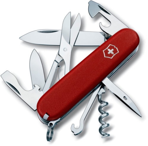
Polyetheretherketone (PEEK) is an engineering thermoplastic with an unusual combination of properties- high mechanical strength, fatigue and creep resistance, excellent chemical resistance, and the ability to perform in high temperatures. It is so robust and does so many things well, it is the most utilitarian ‘Swiss Army Knife’ in the high performance material thermoplastic group.
First synthesized in 1978 by Victrex, it quickly became an excellent alternative to imidized materials (VESPEL® PI, Torlon® PAI). Offering lower cost and superior chemical and hydrolysis (steam) resistance, PEEK is an ideal material for seals, bearings and insulators in oil/gas/chemical processing and other high temperature/pressure applications. PEEK offers higher strength than fluoropolymers (Teflon®) at room and elevated temperatures.
There was only one resin source at the time, so pricing was high and general industry acceptance was slow. In recent years, new sources have introduced PEEK based materials, reducing the price and accelerating application development, making it attractive to more markets.
Processing techniques have also increased with shapes now being available via injection molding, extrusion, and compression molding.
Unfilled PEEK has the highest toughness and elongation of all the PEEK materials, and by itself has good bearing & wear properties. The most popular filled grades are 30% glass filled, 30% carbon fiber filled and a bearing grade with a carbon/graphite/PTFE additive package.
The addition of fiber reinforcement gives PEEK dimensional stability approaching that of metals.
Here’s a brief comparison of the properties of extruded PEEK variant shapes (at 73⁰F):
PROPERTY | Unfilled PEEK | 30% Glass Filled PEEK | 30% Carbon Filled PEEK | Bearing Grade PEEK |
Tensile Strength | 16,000 | 14,000 | 19,000 | 11,000 |
Elongation % | 40 | 2 | 5 | 2 |
Flexural Strength | 25,000 | 23,000 | 26,000 | 27,500 |
Heat Deflection Temperature ⁰F | 320 | 450 | 518 | 383 |
Coefficient of Thermal Expansion | 2.6 | 1.2 | 1.0 | 1.7 |
Dynamic Coefficient of Friction | .32 | n/a | .20 | .21 |
| Relative Wear Rate | 375 | n/a | 150 | 100 |
PEEK products are found in highly critical applications from High-Performance Liquid Chromatography columns to food applications as unfilled PEEK is FDA and USDA compliant. It is one of the few plastics compatible with ultra-high vacuum applications, which makes it suitable for aerospace applications ultra-pure specialty grade PEEK is considered an advanced biomaterial used in medical implants, used with a high-resolution magnetic resonance imaging (MRI), and for creating a partial replacement skull in neurosurgical applications.
Have a need for high performance at high temperatures? Call the experts at WS HAMPSHIRE to walk you through the candidate material selection process. You’re in the right place!
Tom Connelly is a self proclaimed “Street Engineer’ with over 40 years in the plastics industry.


