Skip to Content
Exit

Author Archives: KevinP

  1. Understanding CNC Machining Tolerances to Maximize quality, reduce cost, and navigate design challenges

    Leave a Comment

    Eli Whitney, the inventor of the cotton gin, is credited with the concept of interchangeable parts. During a presentation to the United States Congress in 1801, he illustrated how all of the components needed for an assembly should be produced according to a set of exacting standards— in other words, to specific dimensions and tolerances—thus ensuring that the firing pin or gun barrel from one musket will fit into any other musket. His idea helped pave the way for the Second Industrial Revolution and what became known as the American System of Manufacturing, which has the standard method of part design and print for almost two centuries.

    Although the concepts of component interchangeability and dimensional tolerancing have since become an accepted part of manufacturing, unfortunately, the lack of understanding and proper use of dimensional tolerancing can cause many problems. For instance, an overly stringent tolerance might require that parts go to a secondary operation and/or extra “finishing” passes, unnecessarily increasing costs and lead-time. Tolerances that are “too loose” or that aren’t in line with those of mating parts can make assembly difficult if not impossible, leading to required rework, or in the worst case, making the finished product unusable.

    To help avoid these unpleasant situations, this design tip includes some guidelines on how to properly apply part tolerances, along with a few definitions of the more commonly used callouts.


    The World of Engineering Thermoplastic and Thermoset Materials – How They Differ From Metals

    First, it is important to understand that, unlike metals and ceramics, with engineering thermoplastics the property-determining particles are not atoms, atomic cores and ions, but organic macromolecules, and this differs greatly as compared to the lattice structure of metals.

    These macromolecules can also differ within a plastic in terms of their size and chemical structure, meaning that these factors exert a far wider influence on the properties of the material as compared to metals. Most plastics are termed “semi-crystalline”, meaning they have both crystalline and amorphous structures within the material. Such a complex structure enhances some properties (such as impact resistance), but always results in compromises in material stability as compared to metals.

    As a result of these differences, plastics offer lower dimensional stability in comparison to more historically specified

    • Non-metallics have higher coefficient of thermal expansion, lower rigidity and greater elasticity
    • The moisture absorbing properties of plastics, which can result in phenomena such as swelling of the material and the respective dimensions, also have a determining role to play (particularly in the case of polyamides [nylons]).

    Combined, these attributes add to the difficulty of adhering to very tightly specified tolerances during machining, in shipment and in storage. Therefore, proper storage of engineering thermoplastic components over a long period of time (especially in summer months) is required to maintain the dimensions achieved during machining. High heat (over 80F), especially combined with high humidity, is to be avoided.

    To a lesser extent, this is also true of thermoset materials – the various “phenolic” formulations. The fabric or fiberglass matrix makes these more stable than thermoplastics, but still less than metals.

    The recommended guideline to use when determining machining tolerances is a minimum of 0.2% of the nominal value (Tighter tolerances are achievable when using very stable and fiber-reinforced composite materials).

    Standardized Tolerances for CNC Machining

    At WS HAMPSHIRE, our standard machining tolerance is +/- 0.005 in. (0.13mm) on standard L/W/T dimensions. Hole locations and other critical dimensions can be held more closely. This means any part feature’s location, width, length, thickness, or diameter will not deviate by more than this amount from nominal. For example, the 1 in. (25.4mm)-wide bracket you’re planning to order will measure between 0.995 and 1.005 in. (25.273 and 25.527mm) across, while the 0.25 in. (6.35mm) hole on one leg of that bracket will come in at 0.245 to 0.255 in. (6.223 to 6.477mm) diameter.

    When specifying feature locations, be sure to reference the datums, or “start measuring from here”, points. This is usually from one or more edges, making clear where the centering point of a given feature needs to be located.

    Something that usually helps in those discussions is sending us an assembly drawing, and/or drawing of mating parts. This allows cross-reference and can prevent “tolerance creep”, which is where individual tolerances all tend to one side which can hinder part alignment, especially at attachment points.


    Tolerancing Guidelines for CNC Machining

    Also, be aware that these are bilateral tolerances. If expressed in unilateral terms, the standard tolerance would read +0.000/- 0.010 in. (or +0.010/- 0.000 in.) while a limit-based tolerance in our bracket example would be 1.005 / 0.995 in.

    All are acceptable, as are metric values, provided that you spell them out on the design. And to avoid confusion, please stick with one system and use “three place” dimensions and tolerances, avoiding the extra zero in 1.0000 or 0.2500 in. unless there’s an overriding reason to do so, which may require further discussion.

    Surface Roughness Considerations for Machining Tolerances

    There’s more to part tolerancing than length, width, hole size, etc. There’s also surface roughness, which in the standard offering is equal to 63 µ in. for flat and perpendicular surfaces, and for curved surfaces, 125 µ in. or better.

    This is an adequate finish for most uses, but for cosmetic surfaces on certain parts, we’re generally able to improve appearance through adjusting the feeds and speeds of the equipment. For wear surfaces, the material will smooth out during operation. If aesthetics are important, that needs to be specified on the print and understood (samples always help!)

    Geometric Dimensioning and Tolerancing

    Here’s another consideration. As mentioned earlier, we can accept GD&T tolerancing. This provides a deeper level of quality control that includes relationships between various part features as well as form and fit qualifiers. Below are a few of the more common ones:

    • True position: In the bracket example cited earlier, we called out the hole location by specifying X and Y distances and their allowable deviation from a pair of perpendicular part edges.
    • Flatness: Milled surfaces are generally quite flat, but due to internal material stress or clamping forces during the machining process, some warpage can occur once the part has been removed from the machine, especially on thin-walled plastic parts. A reasonable GD&T flatness tolerance controls this by defining two parallel planes within which a milled surface must lie.
    • Cylindricity: For the same reasons that most milled surfaces are quite flat, most holes are quite round, as are turned surfaces. However, using a +/- 0.005 in. (0.127mm) tolerance, the 0.25 in. (6.35mm) hole in the bracket example could potentially be oblong, measuring 0.245 in. (6.223mm) one way and 0.255 in. (6.477mm) the other. Using cylindricity—defined as two concentric cylinders inside of which the machined hole must lie—manufacturers eliminate this unlikely situation.
      • (NOTE – due to composites higher coefficient of linear thermal expansion, sometimes a slight “slot” is preferred as it allows part movement without buckling)
    • Concentricity: The rings on a bullseye are concentric, just as the wheels on your car are concentric to the axle. If a drilled or reamed hole must run perfectly true to a coaxial counterbore or circular boss, a concentricity callout is the best way to assure this.
    • Perpendicularity: As its name implies, perpendicularity determines the maximum deviation of a horizontal machined surface to a nearby vertical surface.


    There are additional considerations to GD&T, including parallelism, straightness, profile, and angularity, all of which should be indicated on the print. Again – composites are less rigid than metals, and slight irregularities will conform to the mating surfaces, so avoid using “metal-think” when specifying these additional features.

    Summary

    • Remember that composites are less structurally stable than metals, which requires composite-specific tolerancing but also allows for greater conformability with mating parts
    • Don’t over-specify tolerances that aren’t actually required, it adds cost rather than functionality
    • Fine-tuning tolerance dimensions in your designs for CNC machined parts can help maximize those parts’ quality and reduce cost

    We at WS HAMPSHIRE are happy to discuss appropriate part dimensioning, as well as material alternatives and other design considerations with your design team – with over 125 years of non-metallic manufacturing experience, we can help! Give us a call!

  2. What Is an Industrial Laminate?

    Leave a Comment

    Industrial laminates are used in a wide range of commercial and industrial applications. WS Hampshire specializes in laminate fabrication, and our Ryertex® composite laminates and TIMCO Technical Plastics brands are known as the best in the industry. From electrical circuit boards and structural panels to bearings, bushings, and wear parts, our industrial laminates deliver reliable performance across diverse industries.

    Overview of Industrial Laminates

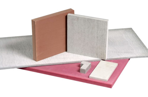
    Industrial laminates are created by stacking multiple layers of materials, typically with a decorative layer on top and a supportive substrate on the bottom. The middle layers may be fabric, paper, or glass fibers bonded together with high-quality thermosetting resins. By combining specific substrates and resins, you can produce properties that aren’t present in the individual substrates or resins alone.

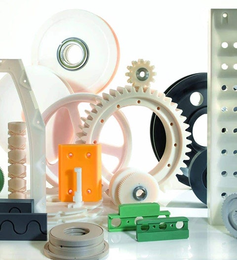
    The resulting sheet material is durable and features high mechanical strength, electrical insulation, machinability, and more. The materials used to create the industrial laminate vary by application and the associated demands placed upon the thermoset composite. These applications include:

    • Bearings
    • Electrical transformers
    • Fixtures
    • Gears
    • Jigs
    • Thermal breaks

    Benefits of Industrial Laminates

    Industrial laminates are trusted because of their unique and customizable characteristics. With the right combination of phenolic, melamine, silicone, or epoxy resin and substrates like canvas, paper, linen, aramid, or fiberglass, you can customize your laminate solution to fit the specific demands of the application. When aesthetics matter, the laminate can include a decorative top layer. Other benefits include:

    • Durability: Industrial laminates can withstand heavy use without deforming or showing signs of wear. They’re lightweight relative to their strength.
    • Chemical Resistance: Certain laminates can be safely and reliably used in environments where they’re exposed to chemicals.
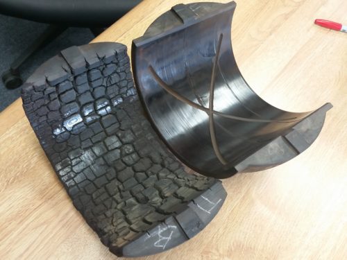
    • Impact Resistance: Industrial laminates are known for their impact resistance and are commonly applications such as steel rolling mills.
    • Machinability: Industrial laminates are easy to work with and are easily machined to suit specific applications and environments.
    • Electrical Insulation: This prized characteristic makes industrial laminates suitable for a range of electromechanical applications.

    Ryertex Industrial Laminates

    Originally known as Bakelite, Ryertex is a group of phenolic thermoset laminate products that were first developed in 1907 by Leo Baekeland. Ryertex has evolved over the years and is now used in everything from electronics to heavy equipment. Traditional applications using Ryertex include buttons, frying pan handles, and telephone mouthpieces. Today, the Ryertex® family of fiber-reinforced plastic composites include a variety of substrate and resin combinations for mechanical, electrical, and heavy industrial applications like bearings, wear liners, structural components, and electrical insulation.

    We also offer other phenolic composite materials, such as Arboron, Resiten, TOPLAB® PLUS, TOPLAB® BASE, TOPLAB® VERTICAL, and Virtuon® sheets.

    Rely on WS Hampshire for Industrial Laminate Fabrication

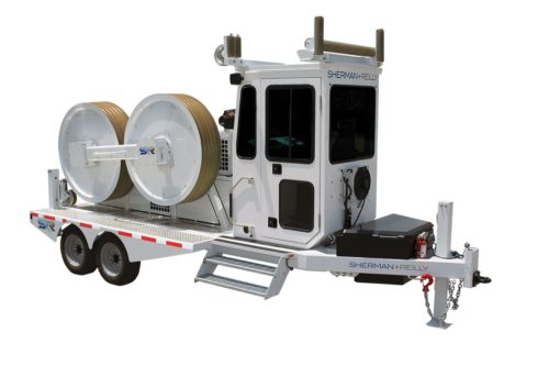
    As a custom fabricator of industrial laminate composites, WS Hampshire has worked with companies in a variety of industries, including paper and lumber processing, oil and gas, forestry, wire and cable, mining equipment, material handling, food and beverage packaging and processing, and more. We have global access to raw materials, and with our extensive capabilities, there is no limit to the sizes, shapes, quantities, and materials that we can produce. We’re here to help with your most complex challenges.

    Contact us today to learn more about industrial laminate fabrication, or request a quote for your project.

  3. What is Aeroponics?

    Leave a Comment

    Aeroponics is a technique used for indoor cultivation in a controlled environment.  There is no growing media like soil or coco and the water tanks so well known in hydroponics are eliminated.  In aeroponics, plant roots are suspended in air and fed directly by a nutrient rich water mist.  Because there is no media, plants do not expel energy searching for oxygen and nutrients, which means that grow faster and with higher yields than in other methods.  The use of mister systems allows for reduction in water consumption of up to 95%.

    Aeroponics was greatly advanced by NASA in the 19990’s for growing in space and is now extremely common for growing vegetables in urban environments.  The technique has long been used in the Clone stage of cannabis cultivation and is now becoming commonplace through the Veg and Flower stages.  High levels of grower control, the ability to grow vertically, and massive reductions in water consumption make aeroponics highly favorable.

    You can learn more on this page or this episode of cannacribs.


  4. Electrical Insulation

    Leave a Comment

    Electrical insulating materials from WS Hampshire take many forms and serve a wide range of application.  From polyester film used in the lighting industry, to corrugated vulcanized fiber in large transformers, to high temperature composites in the electric arc furnace of a modern steel mill.  Our extensive capabilities allow us to slit, roll, punch, form or CNC machine insulating materials into parts per your specifications.

    Contact us today to learn more about how our material and fabrication expertise can help you and your team.

  5. This is not a bearing failure…

    Leave a Comment


    It may be ugly, but this Ryertex bearing was NOT A FAILURE!  Follow here to see how this bearing set replaced bronze and gave one mill the ability to reduce the risk of tens of thousands of dollars in lost production and damaged equipment.

  6. Nylon Cable Pulling & Tensioning Rollers

    Leave a Comment

    Cable Pulling/ Tensioning Rollers

    Cable pulling equipment in the electric, telecommunications, and related industries use rollers to support the line being installed and for directional changes to protect the line from damage. This includes support blocks, snatch blocks, corning arrays/quadrants, and boom point roller-type sheaves on a variety of stringing equipment extensions.  These rollers were initially made of steel or aluminum, but corrosion damaged lines and safety concerns due to part weight led to changes. Rubber and urethane rollers have been used, but they have limitations caused by weathering, chemical attack, and wear.  

    Using nylon in place of steel, rubber, or urethane allows for improved performance and operational efficiency as nylon rollers are lightweight and will not cause damage your cable due to corrosion and wear.

    What applications are you working on where this may apply?

  7. What are Timco Technical Thermoplastics?

    Leave a Comment

    Thermoplastic Parts

    Engineering plastics are a form of polymer that are well known for their high mechanical strength, versatility, and ability to be melted and reformed into other shapes.  For decades, engineers have seen plastics replace metal in applications where weight reduction, corrosion resistance or low coefficient of friction is needed to reduce wear on mating parts.

    Plastics are lightweight so they are safer to maintain than steel and can reduce noise and vibration levels. Options exist to produce parts from fiber reinforced polymers as well as those that are self lubricating which can enhance the performance of plastics. These features help provide longer part life for the entire system, leading to cost savings for equipment manufacturers and end users.

    For example, a significant reduction in the weight of sheaves and wear pads will increases the lifting capacity of cranes or aerial work platforms and may offer a reduction in power requirements. Additionally, the handling and assembly of these parts is made safer as most plastics are one seventh the weight of steel.  Additionally, plastic materials cause very little wear on the contacted surface as seen where wire rope will last two to three times longer when plastic sheaves are used instead of steel. Scheduled maintenance for lubrication of parts is often reduced or eliminated completely when components are manufactured from plastics.

  8. Thermal Insulation Applications

    Leave a Comment

    CS85 Calcium Silicate Board

    As a full service provider of non-metallic materials, WS Hampshire is not limited to Ryertex and Timco Technical Thermoplastics that you probably know us best by.

    WS Hampshire supplies asbestos free thermal insulation boards for applications such as platen presses, foundries, glass handling, molding machines, fire protection, or customized applications with temperatures up to 1,800ºF.

    Materials include various Marinite, Glastherm, Transite, Mica, or CS85 and we can provide full sheets, or custom fabricated parts.

    Let us know what you are working on today and our team will provide the right insulating board for your specific application.

  9. “Dry” Versus “Conditioned” Nylon Explained

    Leave a Comment

    European cast nylon producers, and injection molding resin guides, report both “dry” and “conditioned” data for nylon-based materials which are hygroscopic (absorb moisture from the air) and can absorb upwards of 8% moisture by weight at saturation (compared to 0.8% for acetal).

    This is a completely reversible physical reaction as the higher the humidity, the faster nylon will absorb moisture. However, it only absorbs moisture until it is saturated and can absorb no more.  Conversely, it releases moisture and dries out when exposed to dryer air.

    Under normal conditions, nylon will reach equilibrium in a short period of time, though time will vary depending on thickness.  However, “equilibrium” is a relative term given its environment at a given time.  So, equilibrium will vary from Minnesota to Louisiana, and from winter to summer.

    Dry and conditioned data

    Nylons are semi-crystalline polymers, with both crystalline and amorphous regions. The tight crystalline regions give nylon much of its strength, stiffness and wear resistance.

    The amorphous regions absorb the water, which then bonds to the polymer chain and force the crystalline structures apart.  The result is nylon parts that swell and show diminished mechanical properties. Water actually acts as a plasticizer, making the nylon softer while increasing toughness and elongation. Since these effects happen when polyamides are exposed to moisture, they must be considered when designing a part.

    What is the difference between data quoted for dry and conditioned data for plastic materials? And why is this most significant for nylons

    Dry: Data with equivalent moisture content as when it was run (typically <0.2%).

    Conditioned: data after absorbing environmental moisture at 50% relative humidity prior to testing.

    Effect of moisture on properties

    In general, as moisture content rises, impact strength and other energy absorbing characteristics increase. Some other properties decline

    Variation of properties of nylon 6 as a function of humidity

    Dimensional stability

    When designing nylon components, it is important to consider that dimensions will be dramatically affected by temperature and humidity.  This is especially so on long parts. If the dimensional change is unacceptable, you should consider acetal (POM) or polyester (PET) as alternative materials as they provide additional stability in wet environments.

    At room temperature and 50% relative humidity, equilibrium moisture content for nylon tends to remain around 2%, which corresponds to an increase in size of roughly 0.5 – 0.6%. Under similar conditions, acetal absorbs roughly 0.2% moisture by weight and grow around 0.2%.

    Variations between nylon grades

    How much the different properties change depends a great deal on the chemistry of the polymer itself. Nylon types include 6, 6/6, 4/6, 6/12, 11, and 12 (types = number of carbon atoms in the molecule) Polyamide 12, for example, doesn’t absorb as much moisture as Polyamide 6, so Polyamide 12’s properties don’t fluctuate as much with moisture.

    Absorption of Moisture by Nylons by Weight % at 50% R.H. and Saturation @ 23°C (resin data)

    Additionally, as nylon absorbs moisture beyond equilibrium, its surface becomes “amorphous” (spongy), and wear resistance is lower. The addition of liquid or solid lubricants to the nylon offsets most of the decrease.

    Need help deciding what to use? The experts at WS HAMSHIRE can explain this and more, so you can make the best material decisions for your needs! Call us – you’re in the right place!


    Tom Connelly is a self proclaimed “Street Engineer” with over 40 years in the plastics industry.

  10. Happy Thanksgiving

    Leave a Comment


    Dear customers, vendors, and partners,

    Thank you for allowing us to do what we do.  As we enter the Thanksgiving week, we are reminded again that we would not be in the amazing position that we are today without the trust, support, and commitment that we receive from you every day.  Whether you are customer number one, a supplier that we only buy from sporadically, or somewhere in the middle, please know that we are thankful for all that you do in allowing us to succeed.  We truly could not do it without you.

    From our team to yours, have a Happy Thanksgiving!

    -WS Hampshire